
 under dash relay testing, how do I test the function of the relays |
|
|

|
Porsche, and the Porsche crest are registered trademarks of Dr. Ing. h.c. F. Porsche AG.
This site is not affiliated with Porsche in any way. Its only purpose is to provide an online forum for car enthusiasts. All other trademarks are property of their respective owners. |
|
|
  |

| jeff dodge |
 Oct 15 2026, 02:12 PM
Post
#1
|
|
Newbie  Group: Members Posts: 41 Joined: 5-September 24 From: middleton,WI Member No.: 28,332 Region Association: None  |
I want to test the individual relay function at the back side of the fuse panel. I want to do this while they are removed so that there are no wiring abnormalities that might interfere with resaults. How can I do this? Thanks
|
   |

 
|
| 930cabman |
Oct 15 2026, 03:28 PM
Post
#2
|
|
Advanced Member Group: Members Posts: 4,865 Joined: 12-November 20 From: Buffalo Member No.: 24,877 Region Association: North East States 
|
QUOTE(jeff dodge @ Oct 15 2026, 02:12 PM)  I want to test the individual relay function at the back side of the fuse panel. I want to do this while they are removed so that there are no wiring abnormalities that might interfere with resaults. How can I do this? Thanks I can't recall exactly, but checking with a VOM will provide some information, and powering will provide more info. sorry for the lame response, but there is continuity between certain pins |
|
|
|
| Superhawk996 |
Oct 15 2026, 08:25 PM
Post
#3
|
|
914 Guru Group: Members Posts: 8,144 Joined: 25-August 18 From: Woods of N. Idaho Member No.: 22,428 Region Association: Galt's Gulch
|
There is more than one type of relay attached to the fuse panel. Example: high beam relay, seat belt buzzer depending on year, hazard flasher, etc.
However - a couple of common themes: 1) they all can be bench tested 2) they usually have the relay schematic printed or etched into the case (red arrow) 3) the pin numbers are usually marked next to the pins 4) look up the schematic in the Haynes or factory manual or by part number online if not marked on the case. Here is example of the standard Bosch automotive relay that would typically control fog lights, horn, etc. Pins 85 & 86 are the control solenoid Pin 30 is the power feed in Pin 87a is the normally closed connection to pin 30 Pin 87 is the normally open connection to pin 30 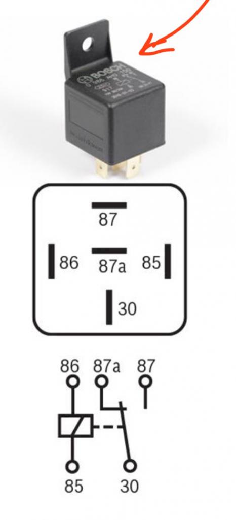 Here’s a link to Jeff Bowlsby’s site that may help you with relay identification. https://bowlsby.net/914/Classic/zTN_Elect_R...inFusepanel.jpg |
|
|
|
| DennisV |
Oct 16 2026, 02:46 PM
Post
#4
|
|
Senior Member Group: Members Posts: 1,040 Joined: 8-August 20 From: Santa Rosa, CA Member No.: 24,575 Region Association: Northern California
|
QUOTE(jeff dodge @ Oct 15 2026, 01:12 PM) I want to test the individual relay function at the back side of the fuse panel. I want to do this while they are removed so that there are no wiring abnormalities that might interfere with resaults. How can I do this? Thanks I was just researching this for horn troubleshooting. This video isn't very polished, but it is helpful. Refer to @Superhawk996 diagram, your relays should be numbered on the back. You can test your relay with a multimeter, a 12V battery, and two jumper wires. I have also read that you can use 9v battery, or a 12v battery from a cordless tool. You can check whether the internal electromagnet works and whether the relay switches electricity correctly. The steps I'm going to take are: TEST 1 — Relay OFF, normally open side 30–87 should have no continuity. This confirms the relay isn't accidentally sending power. TEST 2 — Relay OFF, normally closed side 30–87a should have continuity. Confirms the relay’s internal switch is properly resting in its default closed position. TEST 3 — Energize Relay: Testing that the relay responds to the horn button. Applying 12V across 86 (+) and 85 (−) should produce a click. This confirms the electromagnet moves the internal switch. TEST 4 — Relay ON With the relay energized, 30–87 should have continuity. Feel free to correct my steps if I've erred. |
|
|
|
| jeff dodge |
Oct 17 2026, 09:59 AM
Post
#5
|
|
Newbie Group: Members Posts: 41 Joined: 5-September 24 From: middleton,WI Member No.: 28,332 Region Association: None |
QUOTE(DennisV @ Oct 16 2026, 03:46 PM) QUOTE(jeff dodge @ Oct 15 2026, 01:12 PM) I want to test the individual relay function at the back side of the fuse panel. I want to do this while they are removed so that there are no wiring abnormalities that might interfere with resaults. How can I do this? Thanks I was just researching this for horn troubleshooting. This video isn't very polished, but it is helpful. Refer to @Superhawk996 diagram, your relays should be numbered on the back. You can test your relay with a multimeter, a 12V battery, and two jumper wires. I have also read that you can use 9v battery, or a 12v battery from a cordless tool. You can check whether the internal electromagnet works and whether the relay switches electricity correctly. The steps I'm going to take are: TEST 1 — Relay OFF, normally open side 30–87 should have no continuity. This confirms the relay isn't accidentally sending power. TEST 2 — Relay OFF, normally closed side 30–87a should have continuity. Confirms the relay’s internal switch is properly resting in its default closed position. TEST 3 — Energize Relay: Testing that the relay responds to the horn button. Applying 12V across 86 (+) and 85 (−) should produce a click. This confirms the electromagnet moves the internal switch. TEST 4 — Relay ON With the relay energized, 30–87 should have continuity. Feel free to correct my steps if I've erred. Thank you! I will give it a shot. |
|
|
|
|
2 User(s) are reading this topic (2 Guests and 0 Anonymous Users)
0 Members:

|
Lo-Fi Version | Time is now: 23rd October 2026 - 03:36 AM |
Invision Power Board
v9.1.4 © 2026 IPS, Inc.