|
|
|
Porsche, and the Porsche crest are registered trademarks of Dr. Ing. h.c. F. Porsche AG.
This site is not affiliated with Porsche in any way. Its only purpose is to provide an online forum for car enthusiasts. All other trademarks are property of their respective owners. |
|
|

  |

| Spoke |
 Dec 18 2025, 10:06 PM Dec 18 2025, 10:06 PM
Post
#1
|
|
Jerry  Group: Members Posts: 7,292 Joined: 29-October 04 From: Allentown, PA Member No.: 3,031 Region Association: None |
During a recent build of 914 foglights I decided to take pictures of each step and post them on the Spokeworks Facebook page. The 914 and 911 foglights are the most labor intensive LED assemblies we do and one of the few products which use small (2.7x2.7mm) high power surface mount LEDs. The assemblies also include a massive heat sink, 350ma dc/dc converter, and LED lenses w/frames.
Doing a build is more efficient if several sets are done at once although I've assembled a single set when time was critical for the customer. For this build, I will assemble 4 sets (8 boards). First up is to set the boards aside. 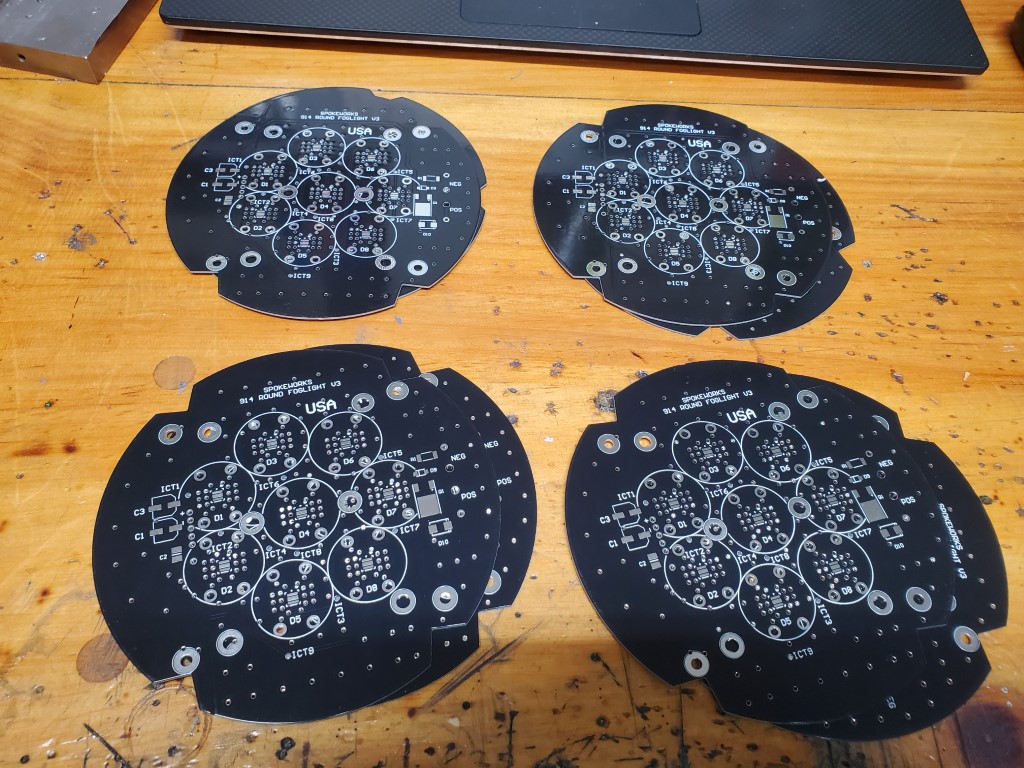 The build has 2 solder processes: - surface mount parts will be placed with solder paste and soldered in an IR oven - Through hole parts include the dc/dc converter and connection wires soldered by hand The surface mount parts are done first. The correct number of components for the eight boards are selected. This step is a pain as the exact number of parts must be pulled from the tape for each component.  The solder paste is put down with a solder paste dispenser by I-extruder. For large components a simple syringe could be used but the tiny LEDs are very sensitive to the amount of paste set down. The dispenser allows adjustment of pressure and duration from 1 to 99. For the LEDs, the settings for both are 1. For the other components the settings are 99. 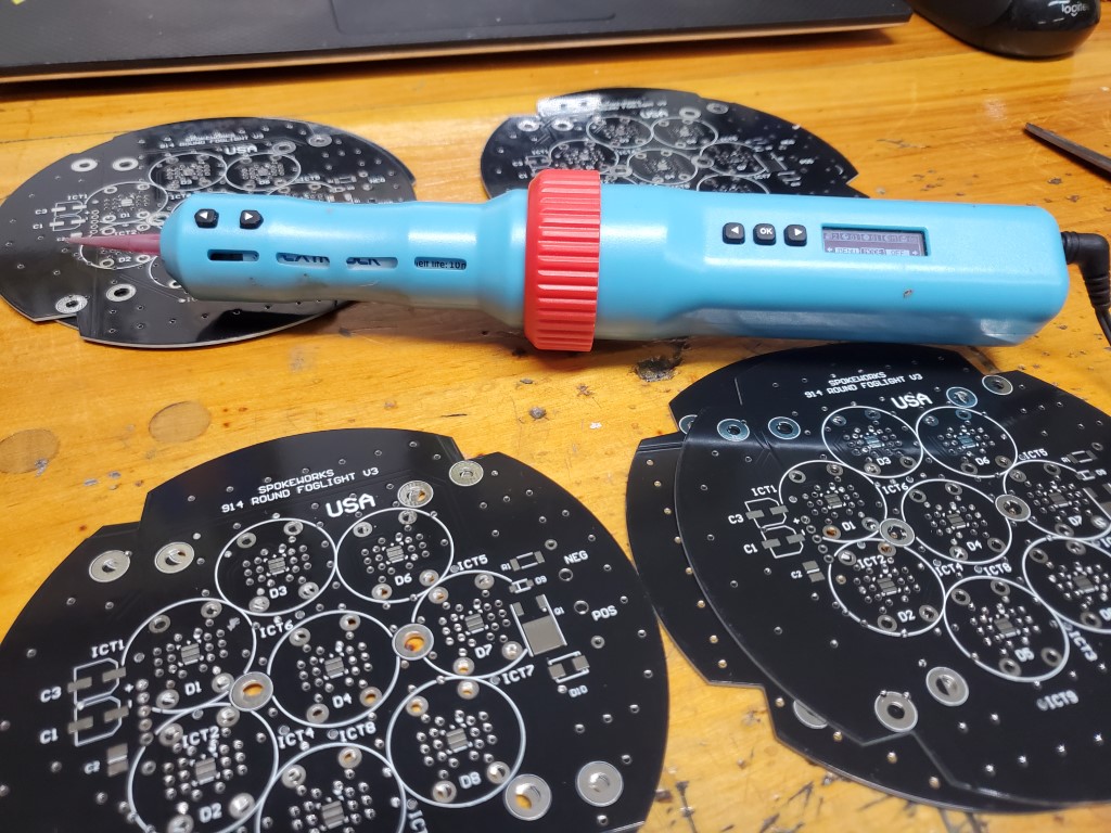 First the paste for the LEDs is put down with pressure and duration both set to 1. 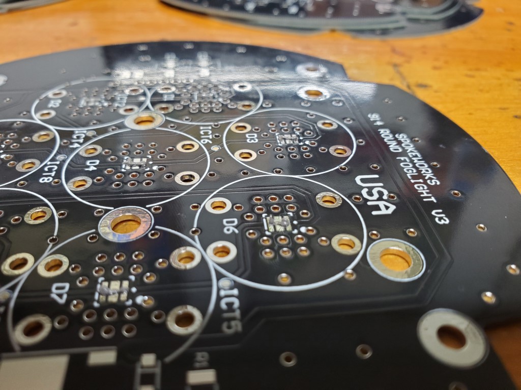 Here's a close-up of one of the LEDs. If too much paste is put down, the paste may puddle under the LED and short out the pads or cause the LED to sit crooked. The center pad is ground for heat removal. The array of vias reduce the thermal resistance of the FR4 board to the heat sink on the bottom of the board. 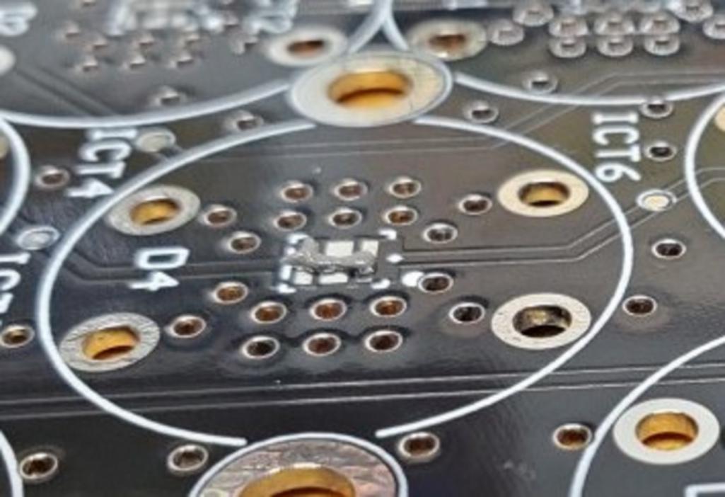 After the LED paste is down, then set the dispenser to 99 for the rest of the components. The paste is not very obvious in the picture although a zig zag of paste can be seen on the Q1 MOSFET pad at the bottom. 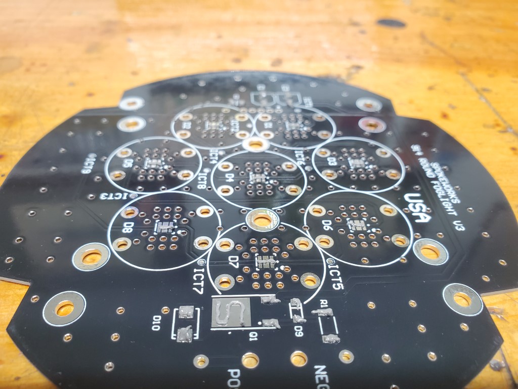 Once all the paste is down on every board, components are selected one board at a time. First step is to place the component near where they will go.  The next step is to place each component on its footprint with a set of tweezers.  All the surface mount components are on their footprints. The paste acts a bit like weak glue and the components will not move but can be easily bumped if not careful. The board is ready for the IR oven. 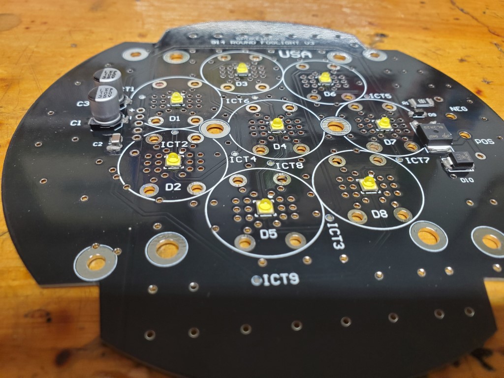 The IR oven can handle one board at a time. The total cook time is about 7.5 minutes. When one board is cooking the next board will go through the component placing. 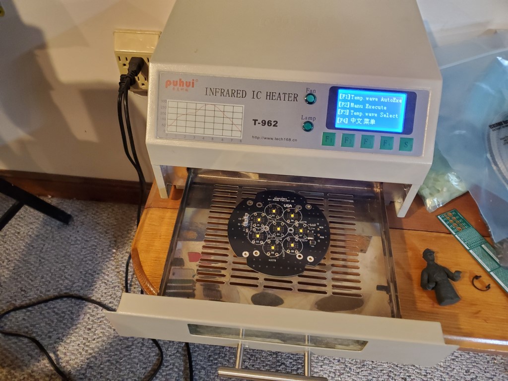 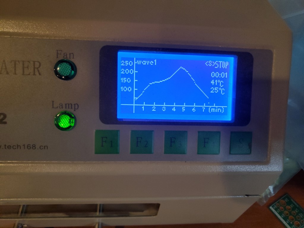 When the board is done in the oven, the LED stack is tested to make sure all LEDs are properly mounted before the dc/dc converter is soldered in. For this test a current limited DC voltage is applied. Start the voltage at zero and increase until about 200ma is flowing. This board looks good. 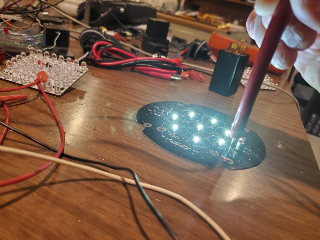 |
   |

 
|
| Spoke |
Dec 18 2025, 10:46 PM
Post
#2
|
|
Jerry Group: Members Posts: 7,292 Joined: 29-October 04 From: Allentown, PA Member No.: 3,031 Region Association: None |
Next step is to solder the through hole components. This includes the dc/dc converter and connection wires.
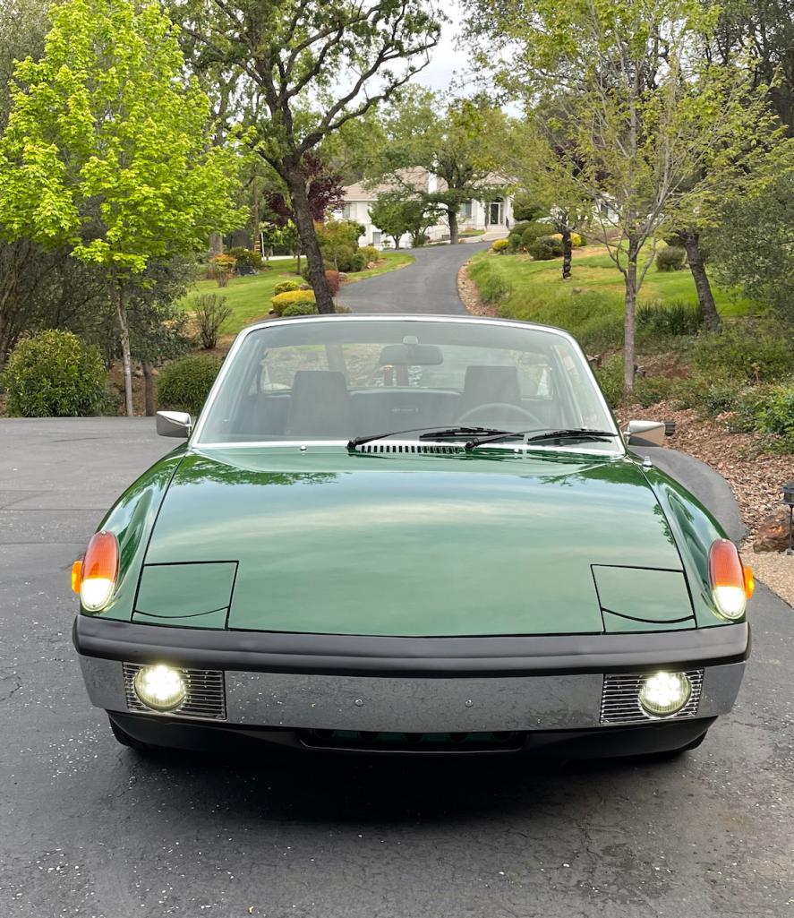
The dc/dc modules are designed and manufactured by LEDdynamics in Randolph, VT. LEDdynamics was one of my customers when I worked for Monolithic Power Systems. An MPS dc/dc converter chip is the heart of the module.  Each board gets one module and 2 wires. The wires are soldered on the back of the board then routed to the back of the board via holes. This provides a nice and simple strain relief for the soldered connections. Notice the heat sink area devoid of solder mask to provide a low thermal impedance to the heat sink.  Now is the first time the entire electronics can be tested. The board is placed face down because the LEDs are so bright they are dangerous. Without the heat sink the board can only be powered for a few minutes. 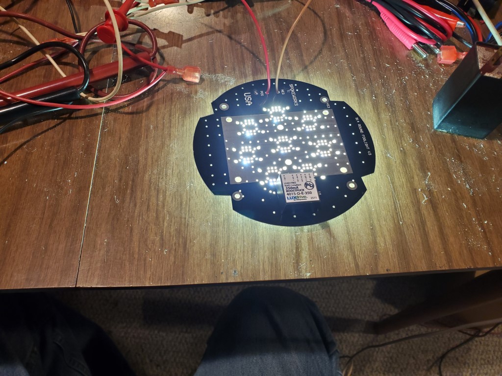 The boards only take about 8.5W. This is compared to the 35W OEM bulbs. The LEDs are about 2x as bright as the bulbs. 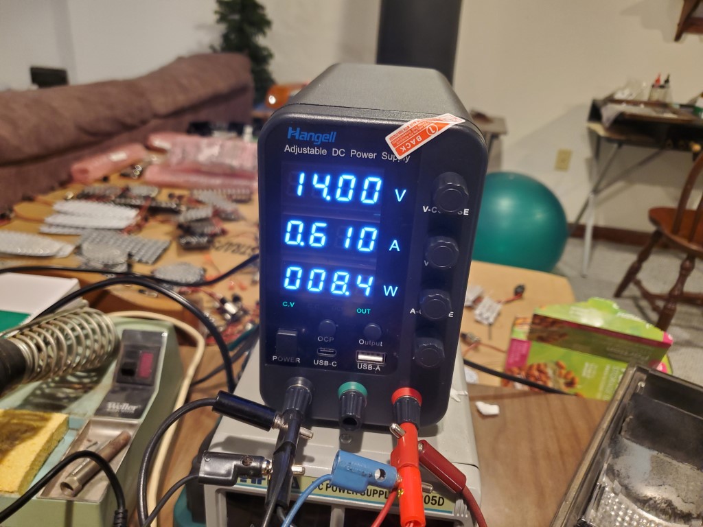 After testing the board get a double alcohol bath to clean any residue mainly from the hand soldering. Each bath takes about 15 minutes. 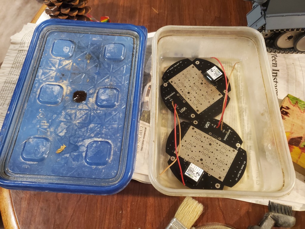 While the boards are taking a bath, time to prepare the heat sinks. Each heat sink is attached to the board with 6 screws. A 3d-printed guide allows quick drilling of the holes although each guide only lasts about 6 heat sinks before needing replaced.  Once the holes are drilled, a drop of oil is placed in each hole to lubricate the tap. A cordless drill makes quick work of the tapping process. 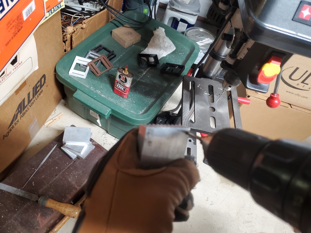 The tapping process causes the aluminum to bulge up around the hole. This needs to be filed down so the heat sink makes good contact with the board. After filing, the heat sinks are washed in a bucket with laundry detergent to remove loose particles and any lingering oil. 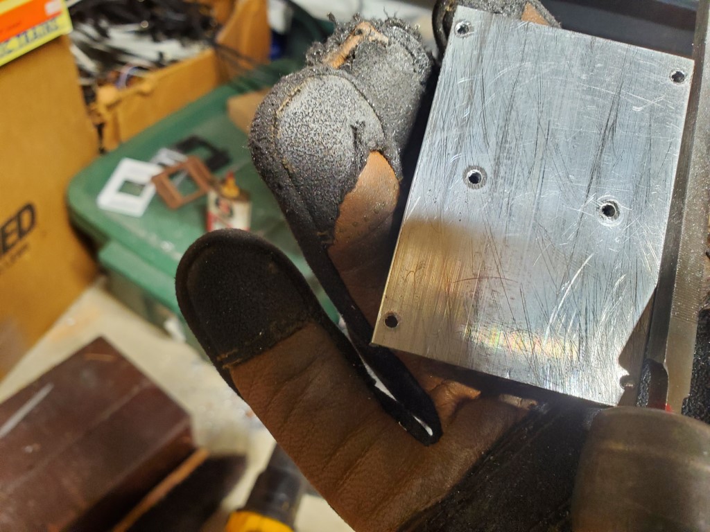 Thermal conductive paste is applied to the heat sinks before mounting on the boards.  The next step is to epoxy the LED lens holders to the board. 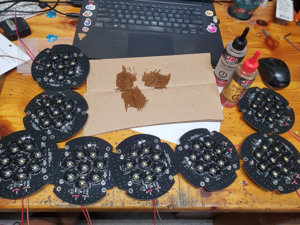 A dab of superglue is applied to both large capacitors and the dc/dc module to dampen vibrations. This view also shows the LED lens holders.  At this point the foglight is basically done. Conformal coating is applied to both sides. Covers protect the heat sink, dc/dc module, and the LEDs.   The LED lenses are now attached. 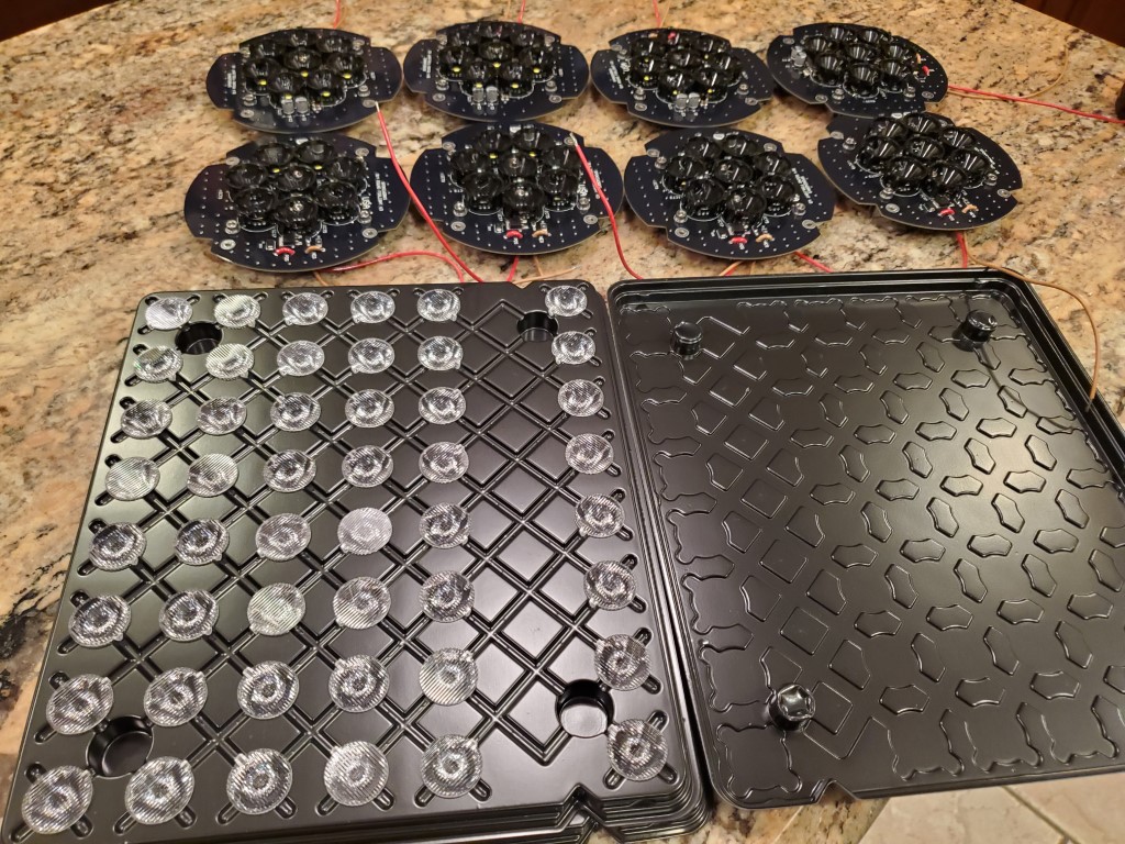 Lenses are required for each LED since the LED 1/2 power angle is 150 degrees or 75 degrees from the center in all directions. Here's the light output without lenses on the ceiling. The round unit is a flush light. I couldn't get far enough away to see the edges of the nature LED output.  Now the same picture with the lenses installed shows the light pattern of the foglight.  While the board assembly is in progress, printing of the foglight lens fixture is done. 3 fixtures are used for each set. One for each board and a spare. Each fixture takes about 50 minutes to print. 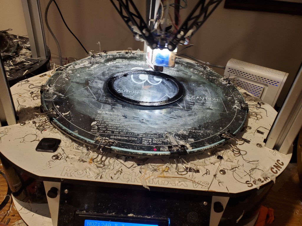 |
|
|
|
| Spoke |
Dec 18 2025, 10:55 PM
Post
#3
|
|
Jerry Group: Members Posts: 7,292 Joined: 29-October 04 From: Allentown, PA Member No.: 3,031 Region Association: None |
A length of heat shrink tubing is used as a sleeve to control the wires and quick disconnect connectors are crimped to the wires.
  The foglight lens fixture is screwed on basically completing the assembly.   The foglight lens holder allows the assembly to fit inside the OEM foglight housing.   The final step is burn-in testing. Each foglight is run for at least 4 hours. Here a pair is tested together.  The total power dissipated is 17W. Not bad considering they're 2x brighter than the OEM bulbs which burn 70W total.  |
|
|
|
| Stratfink |
Dec 19 2025, 01:09 AM
Post
#4
|
|
Member Group: Members Posts: 86 Joined: 27-December 21 From: SoCal Member No.: 26,198 Region Association: Southern California |
Great stuff Spoke,
Seeing the ingenuity in design and the labor (of love) and attention to detail in the build makes me appreciate the product that much more… Best - Joe |
 |
|
| bahnzai |
Dec 19 2025, 05:21 AM
Post
#5
|
|
Member Group: Members Posts: 368 Joined: 26-July 06 From: Columbia, SC Member No.: 6,509 Region Association: South East States |
QUOTE(Stratfink @ Dec 19 2025, 02:09 AM)  Great stuff Spoke, Seeing the ingenuity in design and the labor (of love) and attention to detail in the build makes me appreciate the product that much more… Best - Joe Amen! Jerry’s products are one of the best additions to my car. The geeky side of me loved the build details here. Amazing amount of design and attention to get this just right. Thanks from the community for all you build!! |
|
|
|
| chmillman |
Dec 19 2025, 06:10 AM
Post
#6
|
|
Member Group: Members Posts: 283 Joined: 15-June 24 From: Switzerland Member No.: 28,183 Region Association: Europe |
Yes, great illustrated process! I had no idea there was that much work involved. I didn’t quite understand the purpose of the “conformal coating” that you put on and afterwards seems to be gone again…
And, I have asked this before, but are those SMD LED’s available in warmer color temperatures? Would be good for the “classic” look. In my case the power savings would be even greater as the accessory H3 lamps here are 55W, not 35W. |
|
|
|
| 914Sixer |
Dec 19 2025, 07:23 AM
Post
#7
|
|
914 Guru Group: Members Posts: 9,363 Joined: 17-January 05 From: San Angelo Texas Member No.: 3,457 Region Association: Southwest Region |
Holy smokes, the amount of labor is incredible. (IMG:style_emoticons/default/smilie_pokal.gif)
|
|
|
|
| Cairo94507 |
Dec 19 2025, 08:19 AM
Post
#8
|
|
Michael Group: Members Posts: 10,530 Joined: 1-November 08 From: Auburn, CA Member No.: 9,712 Region Association: Northern California |
I have had Spoke's LED foglight in my car for several years and they are GREAT! I use them as daytime running lights to try to keep idiots from hitting my car as they are taking "selfies" while eating, talking on the phone, etc., while driving. (IMG:style_emoticons/default/beerchug.gif)
 |
|
|
|
| Jamie |
Dec 19 2025, 08:34 AM
Post
#9
|
|
Senior Member Group: Members Posts: 1,174 Joined: 13-October 04 From: Georgetown,KY Member No.: 2,939 Region Association: South East States |
QUOTE(Stratfink @ Dec 18 2025, 11:09 PM) Great stuff Spoke, Seeing the ingenuity in design and the labor (of love) and attention to detail in the build makes me appreciate the product that much more… Best - Joe Ditto, I more fully appreciate my SPOKE fogs now. I had to chuckle about your description of "large capacitors" because back in my photo equipment repair background I sometimes had to deal with flash system capacitors about the size of large fruit juice cans, deadly if zapped when charged. Discharging could be a real "event" if not done correctly! (IMG:style_emoticons/default/screwy.gif) |
|
|
|
| DennisV |
Dec 19 2025, 08:56 AM
Post
#10
|
|
Senior Member Group: Members Posts: 810 Joined: 8-August 20 From: Santa Rosa, CA Member No.: 24,575 Region Association: Northern California |
QUOTE(Spoke @ Dec 18 2025, 08:06 PM) During a recent build of 914 foglights I decided to take pictures of each step and post them on the Spokeworks Facebook page. The 914 and 911 foglights are the most labor intensive LED assemblies we do and one of the few products which use small (2.7x2.7mm) high power surface mount LEDs. The assemblies also include a massive heat sink, 350ma dc/dc converter, and LED lenses w/frames. Very cool of you to take the time to document and share this. I don't think most people appreciate how many components, and how much planning and labor, go into delivering even seemingly simple products. |
|
|
|
|

|
Lo-Fi Version | Time is now: 19th December 2025 - 11:27 AM |
Invision Power Board
v9.1.4 © 2025 IPS, Inc.