|
|
|
Porsche, and the Porsche crest are registered trademarks of Dr. Ing. h.c. F. Porsche AG.
This site is not affiliated with Porsche in any way. Its only purpose is to provide an online forum for car enthusiasts. All other trademarks are property of their respective owners. |
|
|

  |

| GeorgeKopf |
 May 26 2025, 04:25 PM May 26 2025, 04:25 PM
Post
#1
|
|
Member  Group: Members Posts: 207 Joined: 9-February 21 From: Princeton, NJ Member No.: 25,186 Region Association: MidAtlantic Region |
I'm wring my 1973 wiring harness and have a bunch of things installed which seem to be working correctly (i.e. headlights (high & low beam), headlight motors, turn signals, running lights, tail lights)
But (IMG:style_emoticons/default/bootyshake.gif) the turn signal indicators are always on! I've traced the flow of current from the fuse panel (red with white stripe) to the hazard switch, from there (red) to the relay and from there to the turn signal indicators (blue with white stripe). 47 is the relay 31 is the hazard switch 22 is the turn signal lights 26 is the steering column switch 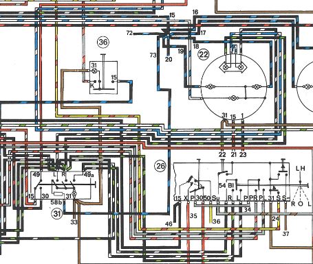 I have two relays and both seem to work fine. When I pull out the hazard switch the indicators and lights all blink. When I set the turn signal that side blinks. I have two hazard switches and both behave the same way. As soon as I connect the red and red/white wires the turn signal indicators come on. With the knob pushed in, I have continuity between the red/white (power in) and the red (power out to the relay). With the knob pulled out, I have continuity between the black/red (power in) and the red (power out to the relay). (IMG:style_emoticons/default/confused24.gif) More information: I have cleaned all grounding studs. I disassembled one of the relays and cleaned it. If I disconnect all of the wires from the hazard switch except for the red/white and the red, the signal indicators come on and stay on. Doesn't this mean that my relay is bad? It should be getting power so that it can feed the turn signal indicators when the turn signals are set. It seems that the relay is allowing the input power to the blue/white wires when it shouldn't. If so, is there a good way to test or repair them? Thanks in advance for any advice. George |
   |

 
|
| 904svo |
May 26 2025, 05:21 PM
Post
#2
|
|
904SVO Group: Members Posts: 1,125 Joined: 17-November 05 From: Woodstock,Georgia Member No.: 5,146 |
jUST A wag check that the brown wire is connect to the gauge case wich is ground
|
|
|
|
| Superhawk996 |
May 27 2025, 05:26 AM
Post
#3
|
|
914 Guru Group: Members Posts: 7,113 Joined: 25-August 18 From: Woods of N. Idaho Member No.: 22,428 Region Association: Galt's Gulch |
Simplified wiring diagram from Spoke
 Take note of how indicators flow to ground through the opposite side turn signal bulbs. |
 |
|
| Superhawk996 |
May 27 2025, 05:29 AM
Post
#4
|
|
914 Guru Group: Members Posts: 7,113 Joined: 25-August 18 From: Woods of N. Idaho Member No.: 22,428 Region Association: Galt's Gulch |
QUOTE(GeorgeKopf @ May 26 2025, 06:25 PM)  If I disconnect all of the wires from the hazard switch except for the red/white and the red, the signal indicators come on and stay on. Doesn't this mean that my relay is bad? No There are lots of other ways the wiring could be screwed up and sending power or grounds to the indicator lamps. |
|
|
|
| rfinegan |
May 27 2025, 05:51 AM
Post
#5
|
|
Senior Member Group: Members Posts: 1,079 Joined: 8-February 13 From: NC Member No.: 15,499 Region Association: MidAtlantic Region |
ON or blinking?
My problems have allows been a bad flasher /hazard relay See diode in the flasher circuit. This results in the light on but not blinking till the signals/ flashes are commanded on and then they blink. But previous owner issues my be the cause too If always blinking look at the parking brake on brake pressure switch on |
|
|
|
| Superhawk996 |
May 27 2025, 06:00 AM
Post
#6
|
|
914 Guru Group: Members Posts: 7,113 Joined: 25-August 18 From: Woods of N. Idaho Member No.: 22,428 Region Association: Galt's Gulch |
QUOTE(rfinegan @ May 27 2025, 07:51 AM) See diode in the flasher circuit. ?? There is no diode in the flasher circuit. Are you referring to the transistor symbol on the flasher / relay (In Spokes diagram) that indicates the flasher is outputting a 12v on / 0v off pulse ? |
|
|
|
| rfinegan |
May 27 2025, 08:55 AM
Post
#7
|
|
Senior Member Group: Members Posts: 1,079 Joined: 8-February 13 From: NC Member No.: 15,499 Region Association: MidAtlantic Region |
My bad, not a diode but replacement did fix my lights on. been dim since I have had my car for 10 years.. Now it works as expected after replacement. Spoke set me on the right path....
|
|
|
|
| GeorgeKopf |
May 27 2025, 07:11 PM
Post
#8
|
|
Member Group: Members Posts: 207 Joined: 9-February 21 From: Princeton, NJ Member No.: 25,186 Region Association: MidAtlantic Region |
@Superhawk996
Thanks for the simplified diagram. I really like that it shows the internals of the hazard relay clearly. My symptoms could be explained if gate L is stuck closed. @rfinegan Thank you for your experience. My symptoms exactly match yours. My turn signal indicators are always on. I'm going to order a new Hazard Flasher relay and hope that fixes it. I'll post the result here. Thanks to everybody who responded. George |
|
|
|
| Superhawk996 |
May 27 2025, 10:33 PM
Post
#9
|
|
914 Guru Group: Members Posts: 7,113 Joined: 25-August 18 From: Woods of N. Idaho Member No.: 22,428 Region Association: Galt's Gulch |
If you’ve already tried 2 flasher relays, and it hasn’t helped why wouldn’t you do some more troubleshooting with a DMM? The chance of both relays being bad in exactly the same way isn’t great.
Alternatively - why not bench test the relays you already have to either prove or disprove your theory that the relay switch pin K has failed closed. This is easily measured with a DMM. Very straight forward to bench test the flasher relays. It is always better to troubleshoot than to blindly swap parts hoping for a solution. Cheaper too! |
|
|
|
| GeorgeKopf |
May 28 2025, 08:46 AM
Post
#10
|
|
Member Group: Members Posts: 207 Joined: 9-February 21 From: Princeton, NJ Member No.: 25,186 Region Association: MidAtlantic Region |
@Superhawk996
I was thinking how I might bench test the relays. Do you know which connector on the unit represents which wire on the diagram? Also, both relays are probably 50 years old. Do they naturally go bad over time? Thanks. George |
|
|
|
| Spoke |
May 28 2025, 09:17 AM
Post
#11
|
|
Jerry Group: Members Posts: 7,169 Joined: 29-October 04 From: Allentown, PA Member No.: 3,031 Region Association: None |
QUOTE(GeorgeKopf @ May 26 2025, 06:25 PM) It seems this is your only issue, correct? There's definitely some wiring issue still. Both indicators should connect to their respective turnsignal at the hazard switch. The other sides of the indicators are tied together and connect to K/C/C2 pin on the flasher. Check these connections by ohming out from the indicators to K/C/C2 pin. QUOTE I have two relays and both seem to work fine. When I pull out the hazard switch the indicators and lights all blink. When I set the turn signal that side blinks. If the turnsignals flash with hazard or L and R turnsignals, then the flasher relay is good. Look at the schematic in post 3. Notice the indicators should be connected to each turnsignal and a common connection going back to the flasher relay. One test to do is to remove the flasher relay and see if the indicators come on with the key. w/o the flasher relay you should have no turnsignals or indicators lit up. |
|
|
|
| Superhawk996 |
May 28 2025, 09:34 AM
Post
#12
|
|
914 Guru Group: Members Posts: 7,113 Joined: 25-August 18 From: Woods of N. Idaho Member No.: 22,428 Region Association: Galt's Gulch |
QUOTE(GeorgeKopf @ May 28 2025, 10:46 AM) Do you know which connector on the unit represents which wire on the diagram? Also, both relays are probably 50 years old. Do they naturally go bad over time? Germans are very good about putting terminal numbers on parts; either on housing or molded in by the terminals themselves Relays are pretty robust devices - would be somewhat unusual to have two that are failed the same way but technically not impossible. If your theory were true you could measure relay terminals with DMM and see if you have continuity between terminals “49” and “k” per schematic in post 3 Terminal k that is on schematic may show up on flasher relay as “c” Likewise - follow Spoke’s advice as quick method as another valid way to help troubleshoot if the problem is coming from The flasher relay. Attached thumbnail(s)  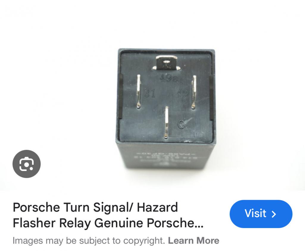
|
|
|
|
| GeorgeKopf |
May 28 2025, 09:40 AM
Post
#13
|
|
Member Group: Members Posts: 207 Joined: 9-February 21 From: Princeton, NJ Member No.: 25,186 Region Association: MidAtlantic Region |
@Spoke
If I remove the flasher relay, the indicators do not come on with the key. With the flasher relay installed, I get power on the blue/white wire to both indicators. Also, disconnecting the turn signal switch didn't make any difference. Thanks. George |
|
|
|
| rfinegan |
May 28 2025, 11:32 AM
Post
#14
|
|
Senior Member Group: Members Posts: 1,079 Joined: 8-February 13 From: NC Member No.: 15,499 Region Association: MidAtlantic Region |
I did use a LED ready hazard flasher, so when I update to LED there will be no surprises.. Mine was a no mode flasher. See Spoke treads for details
IM using stand bulbs and LED IP bulbs at this time -Robert |
|
|
|
| GeorgeKopf |
May 28 2025, 11:51 AM
Post
#15
|
|
Member Group: Members Posts: 207 Joined: 9-February 21 From: Princeton, NJ Member No.: 25,186 Region Association: MidAtlantic Region |
@rfinegan
This is very good information. I'm testing with the normal bulbs but will be switching to LED bulbs at some point in the future. Thank you. George |
|
|
|
| Spoke |
May 28 2025, 02:43 PM
Post
#16
|
|
Jerry Group: Members Posts: 7,169 Joined: 29-October 04 From: Allentown, PA Member No.: 3,031 Region Association: None |
QUOTE(GeorgeKopf @ May 28 2025, 11:40 AM) @Spoke If I remove the flasher relay, the indicators do not come on with the key. With the flasher relay installed, I get power on the blue/white wire to both indicators. Also, disconnecting the turn signal switch didn't make any difference. Thanks. George I would expect the indicators to be off with the relay removed. Quite honestly, I'd bypass the K/C/C2 pin on the relay and just ground the common connection of the indicators to the tach ground. I did this on my '71. I'm still using the OEM flasher with all LEDs with no issues. If you do change to external LEDs the function of K/C/C2 is lost. K/C/C2 is active in the relays as a safety feature to alert the driver of a burned exterior turnsignal bulb. If a bulb is burned out, the relay will not power K/C/C2 during flashing and both indicators will flash together indicating a burned bulb. An easy workaround which I did on my 914 is to remove the common wire at the indicators and tape them off. Then make a pigtail like shown below. The piggyback connector goes under the tach ground (brown wire) and the 2 female spades go to each indicator. The indicators will flash opposite (L on for right turnsignal; R on for lefts). This is easily fixed by pulling the entire light assembly out and put it in the opposite hole. Here's spades for the mod. This is the ground piggyback connector. You need 1 of these. Piggyback Spade This is for the bulb spades. You'll need 2. Female Spade Attached thumbnail(s) 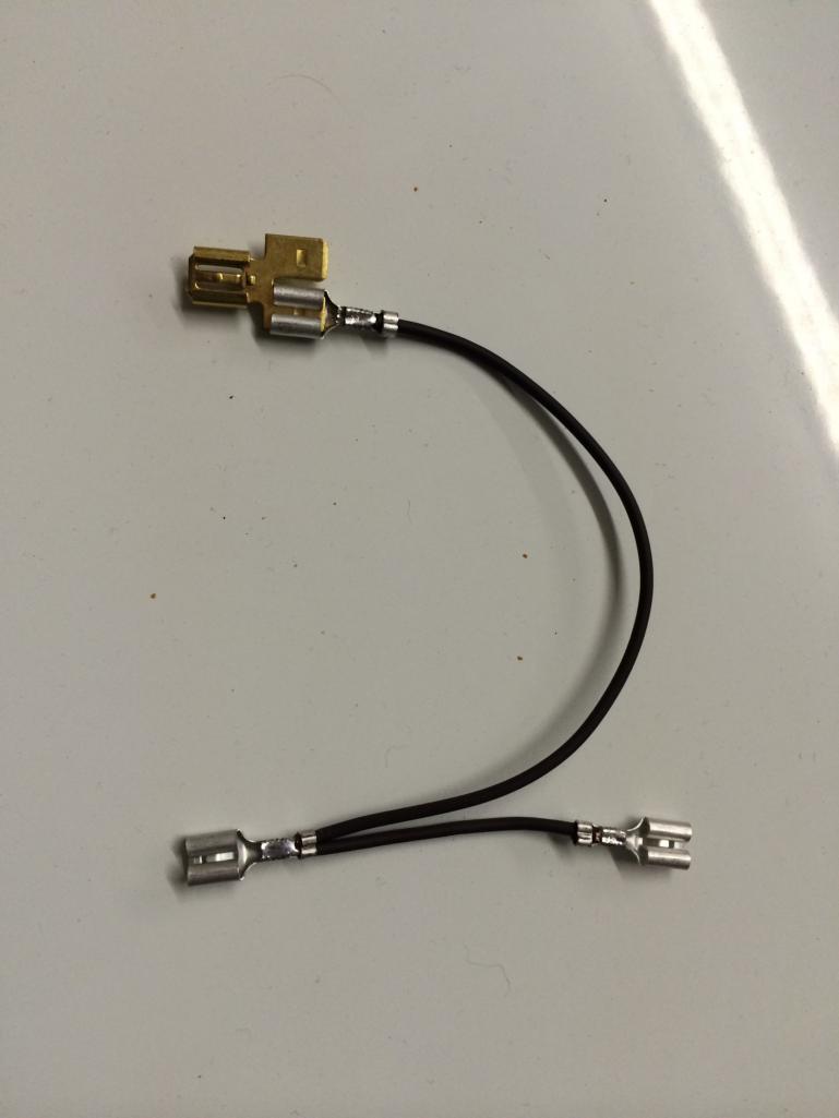 
|
|
|
|
| GeorgeKopf |
May 28 2025, 07:15 PM
Post
#17
|
|
Member Group: Members Posts: 207 Joined: 9-February 21 From: Princeton, NJ Member No.: 25,186 Region Association: MidAtlantic Region |
@Spoke You said:
"An easy workaround which I did on my 914 is to remove the common wire at the indicators and tape them off. Then make a pigtail like shown below. The piggyback connector goes under the tach ground (brown wire) and the 2 female spades go to each indicator." This should be an easy test since my dash is off, and all the gauge wires are exposed. My flasher relay is only labeled: ....49 49a....C ....31.......(see below) 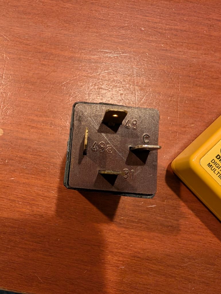 ......................................Relay #1................................Relay #2 Between 31 and 49a:..there is no continuity..................there is no continuity Between 31 and 49:....resistance is 812 ohms...............there is no continuity Between 31 and C:.....resistance is 876 ohms..............there is no continuity Between 49a and 49:..there is no continuity..................there is no continuity between 49a and C:....there is no continuity..................there is no continuity Between 49 and C:......resistance is 850 ohms...............resistance is 48 ohms Lastly, I poked and prodded all the little switches in the mechanisms and some of the above numbers changed significantly. 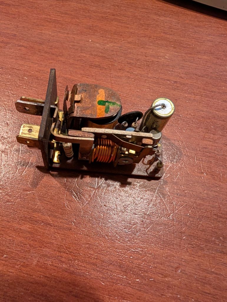 Thanks. George |
|
|
|
| Superhawk996 |
May 29 2025, 02:42 AM
Post
#18
|
|
914 Guru Group: Members Posts: 7,113 Joined: 25-August 18 From: Woods of N. Idaho Member No.: 22,428 Region Association: Galt's Gulch |
QUOTE(GeorgeKopf @ May 28 2025, 09:15 PM) Between 49 and C:......resistance is 850 ohms...............resistance is 48 ohms Neither of those flasher relay measurements looks particularly promising. If your measurements are correct, the one with 48 ohms should lead to indicators that glow much brighter than the other. Good job doing some basic troubleshooting. I’d agree - short of trying to revive those, or to set up a complete bench test inclusive of incandescent lamp loads I’d order a new one. |
|
|
|
| Spoke |
May 29 2025, 07:30 AM
Post
#19
|
|
Jerry Group: Members Posts: 7,169 Joined: 29-October 04 From: Allentown, PA Member No.: 3,031 Region Association: None |
QUOTE(GeorgeKopf @ May 28 2025, 09:15 PM) My flasher relay is only labeled: ....49 49a....C ....31....... This is the same pinout as EP26. EP36 is the same minus the C pin. Out of the box for EP26 the C pin is open and does nothing. I resell EP26 with the C pin connected to ground for separate L and R. For the single L/R indicator cars, the C pin is connected to 49 via the internal relay when active. As mentioned before, the K/C2/C pin only has value for all incandescent turnsignals when it operates properly. If one installs LED turnsignals, the pin is worthless. Also over the years, the efficiency of the coil decreases (the large gauge coil in the picture) for K/C/C2 to the point where an indicator may flash once then both flash together. Unless you really want the alert feature of the K/C2/C pin for burned bulbs, life is simplified by grounding the common connection of the indicators or installing EP26 with K/C2/C pin grounded internally. |
|
|
|
| GeorgeKopf |
May 29 2025, 07:47 AM
Post
#20
|
|
Member Group: Members Posts: 207 Joined: 9-February 21 From: Princeton, NJ Member No.: 25,186 Region Association: MidAtlantic Region |
|
|
|
|
|
1 User(s) are reading this topic (1 Guests and 0 Anonymous Users)
0 Members:

|
Lo-Fi Version | Time is now: 2nd June 2025 - 11:15 AM |
Invision Power Board
v9.1.4 © 2025 IPS, Inc.